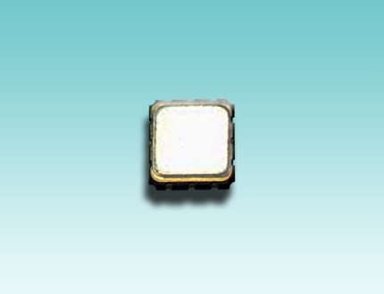
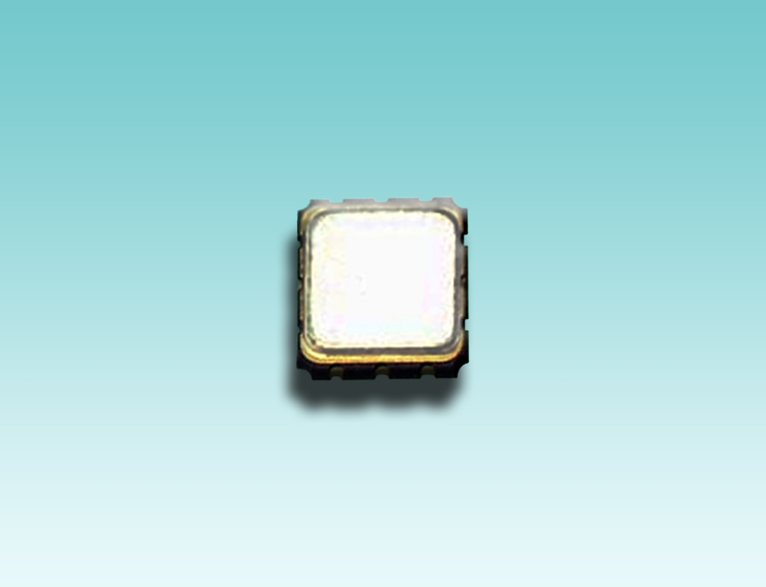
SMD Type SAW Filter
SMD Type SAW Filter for GPS AGSD-SSTC2520 1575.42 MHz for GPS
Maximum Rating:
- 1. Maximum Input Signal Level: +10 dBm
- 2. Maximum DC Voltage: 5 V
- 3. Operating Temperature: -40 ºC ~ +85 ºC
- 4. Storage Temperature: -50 ºC ~ +100 ºC
Electrical Characteristics:
|
Item |
Unit |
Min. |
Type. |
Max. |
|
Center frequency Fc |
(dB) |
- |
1575.42 |
- |
|
Insertion loss within Fc +/- 1 MHz IL |
(dB) |
- |
2.7 |
3.5 |
|
Amplitude ripple (p-p) within Fc +/- 1 MHz |
(dB) |
- |
0.07 |
1.0 |
Attenuation (Reference level from 0 dB)
|
(dB) (dB) (dB) (dB) |
35.0 30.0 30.0 40.0 |
40 37 60 62 |
- - - - |
|
VSWR within Fc +/- 1 MHz |
- |
1.3 |
2.0 |
|
|
Source impedance Zs |
Ω |
- |
50 |
- |
|
Load impedance ZL |
Ω |
- |
50 |
- |
Note1. No matching network required for operation at 50 Ω.
Dimension: (mm)

SAW (surface acoustic wave) filters are electromechanical devices commonly used in radio frequency applications. Electrical signals are converted to a mechanical wave in a device constructed of a piezoelectric crystal or ceramic; this wave is delayed as it propagates across the device, before being converted back to an electrical signal by further electrodes. The delayed outputs are recombined to produce a direct analog implementation of a finite impulse response filter. This hybrid filtering technique is also found in an analog sampled filter. SAW filters are limited to frequencies up to 3 GHz.
Engineers realized that a large number of crystals could be collapsed into a single component, by mounting comb-shaped evaporations of metal on a quartz crystal. In this scheme, a "tapped delay line" reinforces the desired frequencies as the sound waves flow across the surface of the quartz crystal. The tapped delay line has become a general scheme of making high-Q filters in many different ways.


